last updated: 2024-06-26
Hello! Welcome to this blog where we delve into the workings of industrial cameras and their application in classical image processing techniques. We also explore cutting-edge methods utilizing Convolutional Neural Networks (CNNs). Whether you’re looking to build a solid foundation in image processing or expand your knowledge with modern approaches, you’ve come to the right place. Happy reading!
Introduction
Applied Industrial Image Processing (AIIP) is the field focused on extracting information from images. The typical workflow involves capturing images under optimal lighting conditions and camera settings. The next step is image segmentation, such as binarization or edge detection, to eliminate ‘noise’ from the image. This process allows the classifier to make accurate decisions based on the cleaned and segmented image data.
Image Processing Systems
There are three commonly used types of Industrial Image Processing Systems (IPS).
-
Computer-based System: This setup uses an external light source and a camera connected to a computer with installed software that can grab frames from the camera. The advantages include scalable computational power, flexibility in hardware selection, and direct visualization via a graphical user interface (GUI). However, the downsides are the high conceptual effort and increased physical space usage.
-
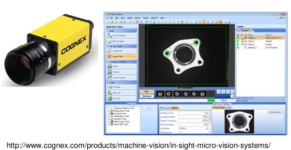
Smart Camera: This system integrates a complete image processing unit, usually including a light source and a lens, within a single casing. Compared to the computer-based system, the smart camera setup requires minimal physical space, making it easy to integrate into most factory environments. But withit comes also some downside frist it is a proprietry software and not all features that somebody might want are included, so there is a dependency and the costs of such a system are usually bigger than the first setup but the needed knowledge is smaller.
-
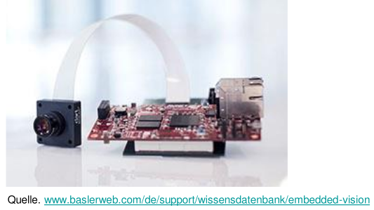
Embedded Vision Systems: Last but not least, there are also embedded vision systems, which are smaller than the other setups and cost less due to their microcontroller-based approach. The only real downside is the high integration effort.
Lightsources
The spektrum of lightsources is divers as the spreptrum of light itself. In this blog we are going to focus on LED’s because they are wiedly used in the domain of AIIP.
Enviromental light is a disturbance for image capturing
Light Emitting Diode
tldr; creating light in different colors through electron-hole-combinations. Band gap of the semiconductor $\to$ wavelength $\to$ colour of light.
\[E_{g}=hf=\frac{hc}{\lambda}\]$\to$
\[\lambda = \frac{hc}{E_{g}}\]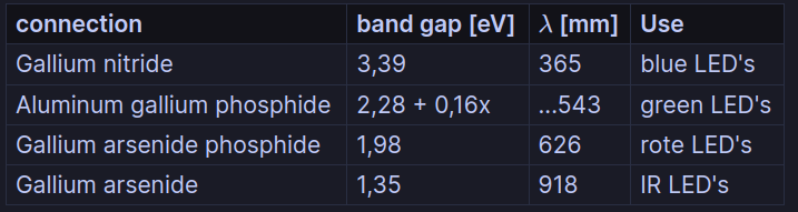
For a deeper dive into LED’s look here.
Light Guidance
A right light direction is essential for to get a clear information from the extracted features.
There are many type of Light Guidance:
-
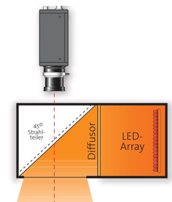
diffuse illumination
the object is not directly illuminated, it is indirect illuminated with a diffusor. a diffusor is a component which scatters light (milkglass)
properties: homogeneous alignment, cracks are illuminated from all side, light intensity is reduced due to diffusor.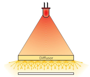
-
direct illumination
properties: high intensity, location-dependent angle of incidence $\to$ only matt objects.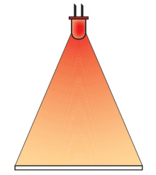
-
focused illumination
properties: high intensity due to focused illumination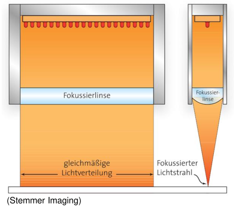
-
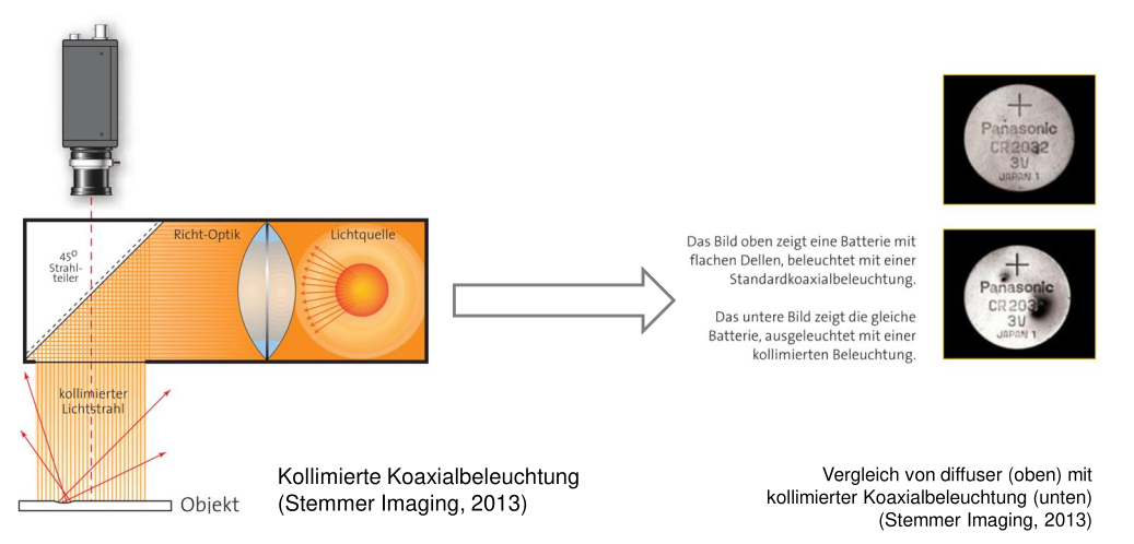
collimated lighting
The light source is within the focal point of the lens.
properties: Images generated that way are rich in contrast. Used in combination with telecentric lenses.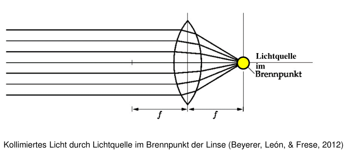
Surface Structure
To decide which kind of illumination is best suited for your specific use case, you need to know the surface structure of your target.
a rough classification is:
- matt flat surface
properties: scattering surface - illumination is non-critical
- glossy flat surface
properties: target acts as mirror $\to$ light source is visible in image - light has to be scattered with a diffusor
- matt uneven surface
properties: depending on the angle of incidence shadow cast possible.
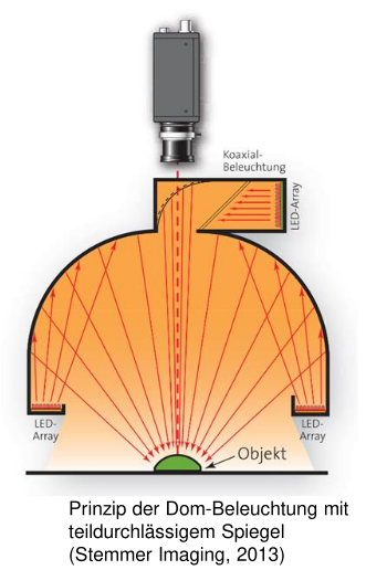
- glossy uneven surface
properties: light has to be diffused -> spezial illumination hardware like a dome lighting.
light solutions
coaxial lighting
Coaxial lighting creates homogeneous illumination on a target object.
coaxial lighting (collimated)
only plain horizontal areas appear bright.
dome lighting
Constructive avoidance of inhomogeneous illumination.
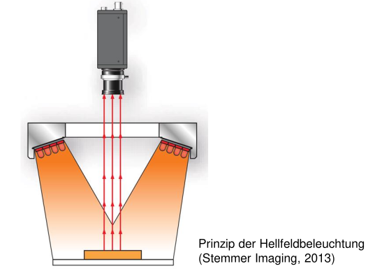
bright field illumination
Horizontal areas appear bright and scratches appear dark.
dark field illumination
Only scattering features appear bright $\to$ Usefull for finding scratches.

Lens and Camera
In this chapter we want to answer the following questions:
- What is a central projection?
- Why is a lens optic more widely used than a pinhole camera?
- How is the illistration law derived and where it is applied?
- How an aperture influences the depth of field?
- what the depth of field is, name its influencing parameters and calculate the depth of field
- for what a telecentric lens is used.
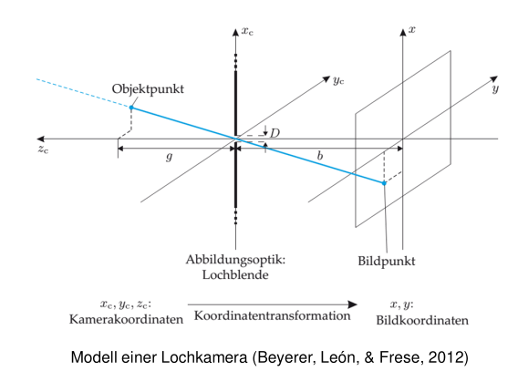
pinhole camera
With a pinhole camera it is possible to capture light trough a hole and to project on a 2 dimensional area. Because of the properties of light knowing the relative position of the target object in regards of the pinhole it is possible to determine properties of the projected object on the 2D area.
This is called central projection. It says that the distance from the object to the pinhole on the x-axis $x_{c}$ divided by the distance $z_{c}$ on the z-axis is equals the relation $\frac{x}{z}$ whereby x stands for the distance between projection and pinhole on the x-axis and z for the distance on the z-axis. Also because the origin of the coordinates lies on the pinhole we need to use a negative sign for the projection side.
\(\frac{x_{c}}{z_{c}}=-\frac{x}{z}\)
The same applies for the y-axis.
\(\frac{y_{c}}{z_{c}}=-\frac{y}{z}\)
=>
With size ratio $V=-\frac{b}{g}$
lenses
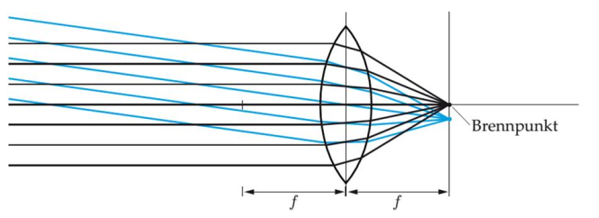
lenses are a special components that are used for a targeted refraction of light. All parallel incoming beams meet a the focal point.
 Lenses are always preferred against pinhole cameras because, a pinhole camera delivers only a sharp image when it has a very small pinhole. The downside of having a very small pinhole is that less light is used for the image, therefore it is very dark.
When dealing with thin lenses, usually a lens is called thin when the thickness of the lens is much smaller than the focal point, then it is possible to use the illustration law.
\(\frac{1}{f}=\frac{1}{g}+\frac{1}{b}\)

statements from the illustration law
cause of depth of field
Target is sharp when it has the distance g.
\(g=\frac{b*f}{b-f}\)
focus
Object can only be sharp when the distance from the sensor and the main plain of the lens have a distance of b.
\(b=\frac{f*g}{g-f}=\frac{f}{1-\frac{f}{g}}\)
special case:
g $\to$ $\infty$ : b $\cong$ f
g $\to$ f : b $\to$ $\infty$
object selection
It is possible to determine the focal point of the lens through the target distance g and the distance between sensor and main plain of the lens.
\(f=\frac{g*b}{g+b}\)
Enlargement
$V=\frac{b}{g}=\frac{f}{g-f}$
with g » f
$V=\frac{f}{g}$
$\to$ enlargment is proportional to focal point
depth of field (DOF)
only objects with a distance $g=\frac{bf}{b-f}$ can be displayed sharp. But this distance can have a small tolerance called $\epsilon$ . The reason for that is that the light still hits the pixel which has some kind of dimensions.
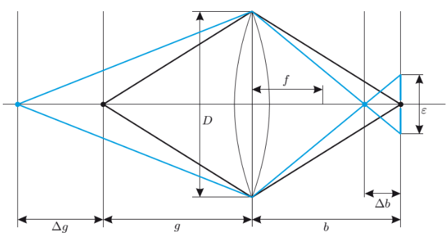
*Tolerable deviation from the focal plane on the far and near sides:
\(\triangle g=\frac{\epsilon *g}{\frac{d*f}{g-f}\pm \epsilon}\)
Usually applies $\epsilon$ « $\frac{df}{g-f}$ $\to$ $k\frac{g(g-f)}{f²}*\epsilon$
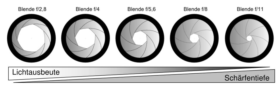
with $k=\frac{f}{D}$
D is the aperture value. The values are potencies of $\sqrt{2}$. That means when increasing the aperture value, the area doubles.
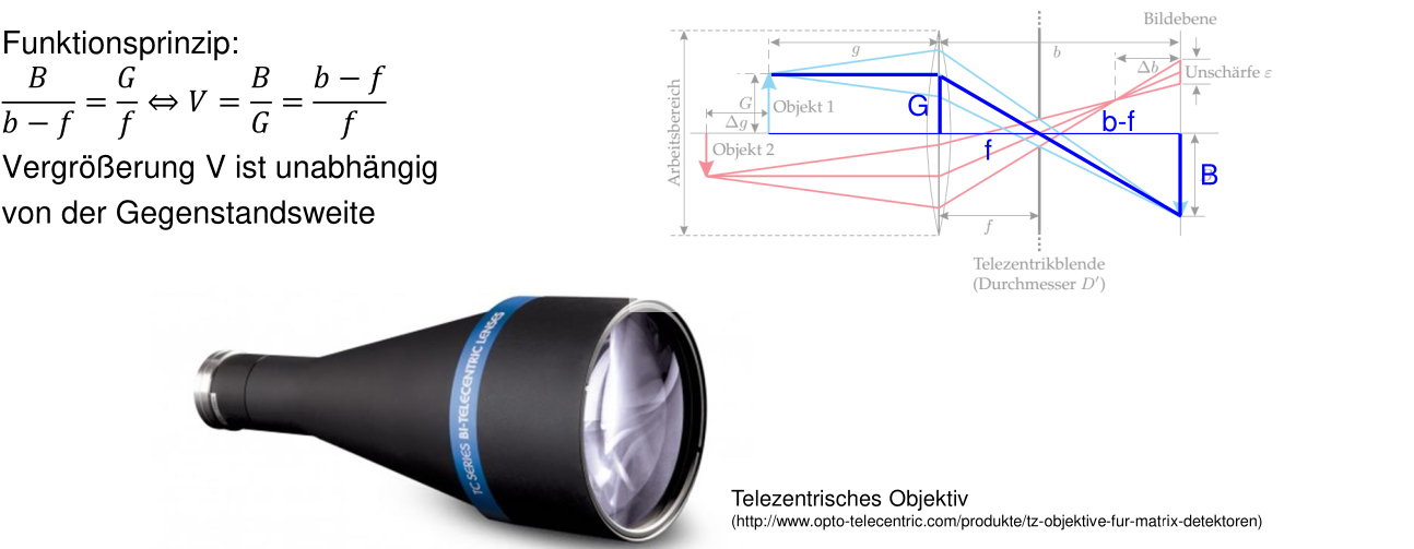
telecentric lens
One of the limitation of normal lens is that the enlargement is dependent of the distance of the target. This can be overcome with telecentric lens.
Camera
consumer camera’s
- focus is on resolution
- integrated image compression (JPEG)
- read image slow #### IP-cameras for monitoring<br>
- compression of images for a lower bandwith
- images capturing only when movement is detected #### indutrial camera<br>
- focus is on unadulterated image reproduction
- no data compression
- high frame rate
Sensor technology
There are two dominant sensor technologies: Charged Coupled Device (CCD) classic technology for high-end cameras. Displaced by CMOS.
disadvantages compared to CCD
- low Fill factor (Proportion of the light-sensitive area in the total area)
advantages compared to CCD
- higher frame rate
- region of interest and reduce noise due to average with more pixels (binning)
- no to low blooming effect
- low energy consumption
- preprosessing on the chip
Rolling Shutter
sequential reading of rows $\to$ distortion by very fast movments newer versions of CMOS-sensor also have Global Shutter
characteristic of camera’s
physical basis
The foundation of light measurement is the property of light of being a particle flow.
The detection of light on a Sensor is a statistical process.
The expected value $\mu_{p}$ is the number of photons which meet on a surface proportional to $A$ (Area), $t$ (Duration), E (Intensity).
\(\mu_{p}=\frac{E*A*t}{E_{Photon}}=\frac{E*A*t}{h*\frac{c}{\lambda}}\)
This is a poisson-distibution, it applies for the varianz: $\sigma²=\mu_{p}$
$\to$ varianz is a measure for light-noise.
$\to$ quantum efficiency $\eta$ describes how many photons generate a electron-hole-pair.
Photon-Transfer-Method

$\mu_{p}$ stands for the photons which are detected by the collector. $\sigma²$ describes the varianz. The photons are converted to a electric signal with a so called quantum efficiency $\eta$. A dark noise is added to the electric signal. This electric nois comes from thermal heating within the camera. Those signals are added up and then empowered with the gain $K$. The resulting signal is then quantized, this also adds a quantization noise. The resulting signal is a digital gray value $\mu_{g}$.
- $\mu_{e}=\eta*\mu_{p}$
- $\mu_{g}=K*(\mu_{e}+\mu_{d})$
SNR (Signal-Noise-Ratio)
\(SNR=\frac{\eta*\mu}{\sqrt{\sigma²_{d}+\frac{\sigma²_{p}}{K²}+\eta*\mu_{p}}}\)
- SNR is almost not dependent of K
- If illumination intensity is high $\to$ $SNR=\sqrt{ \eta*\mu_{p} }$
- That means that if the light source is good, nearly every camera has the same SNR.
- That means that if the light source is good, nearly every camera has the same SNR.
- If illumination intensity is low $\to$ $SNR=\frac{\eta*\mu_{p}}{\sqrt{\sigma²{d}+\frac{\sigma²{d}}{K²} }}$
- proportional to illumination intensity
- proportional to photon number
- It is important that the pixel area is large enough.